Light Clock Version I.
A light source orbits around a circular clock face, casting a ray of light towards a mirror at it’s center. The incident ray is the hour hand and the reflected ray is the minute hand.
| Link | coming soon ↗︎ |
| Role | designer, manufacturer |
| Materials | White Ash Plywood, Raw Unfinished Steel, PLA, Copper, Custom Electronics |
| Info | manufactured at MIT Media Lab |
| Manufacturing | automatic tool change CNC milling, water jet, PCB milling and soldering, 3D printing |
Light Clock Version I.
I conceived and built this clock during my first semester at MIT Media Lab, bringing together my interest in computer-aided design and manufacturing, lighting design and home objects.


Concept
The light clock is a conceptual yet functional object. The initial sketch was minimal, intentionally leaving room to explore different designs. As I translated the concept into a working design, I continually returned to the initial sketch to adhere to it's simplicity and legibility.

Design
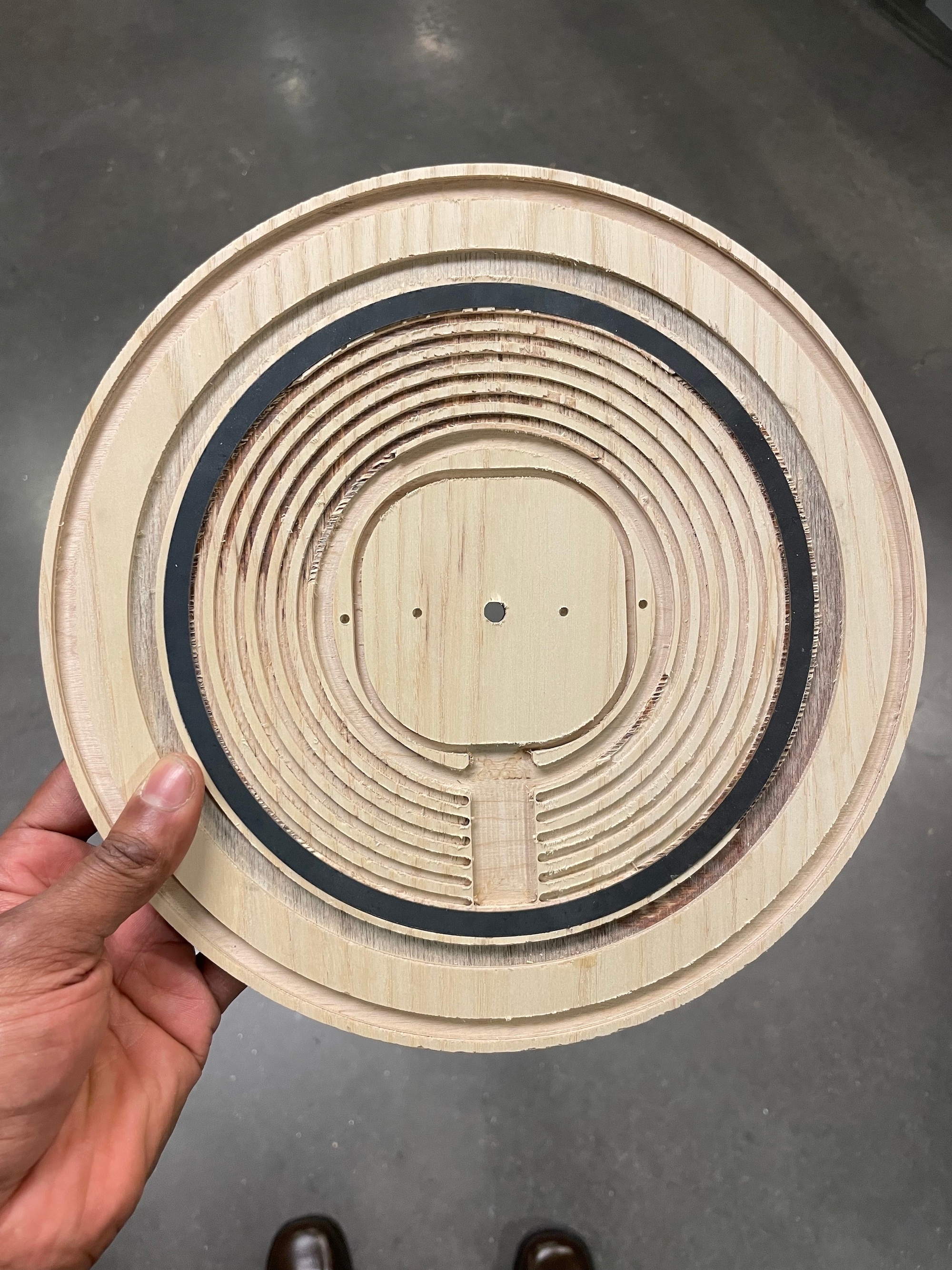
The clock face is white ash plywood which was used as a base for mounting all other components by milling grooves on it's backside. I used an automatic tool change milling machine to achieve precise tool paths for the mounting area for each component.

CAD
I designed the components and electronics in Autodesk Fusion and Eagle. The design called for a light source actuated along a circular rack and pinion using a small stepper motor.

Light
The light source is a single bright LED diode, focused through an aspherical collimating lens. The housing for the light source is attached to the back of the clock face magnetically, via a circular magnet mounted next to the stepper motor and a steel ring embedded in the plywood on the back of the clock face. The light source housing moves on a set of triangularly set bearings.

Electronics
The main electronics circuit drives the central stepper motor that rotates the mirror and the stepper motor that actuates the light source. It implements a SAMD21 microcontroller, two stepper drivers, and some peripheral components for voltage and current regulation.

Stand
The clock stand was cut as a single piece of unfinished steel using a water jet cutter and bent to spec using three different hand-press metal bending machines.

Version I
The first iteration of the clock achieves the intention of the original design by implementing a wired solution for the orbitting light source. A future iteration will make use of the copper rings on the back of the clock as conductive traces to power the light source.

Many thanks to the members of the CBA lab↗︎ at MIT Media Lab for their advice and help throughout the design and manufacturing process.

